First I must acknowledge the resources that this project leveraged:
- The Oxullo Arduino-MAX30100 library and reference code (github.com/oxullo/Arduino-MAX30100), that shows how to set the sensor IR and Red LEDs, and do a callback when heartbeat is detected to read the Sp02 level.
- The OLED display library by ThingPulse (github.com/ThingPulse/esp8266-oled-ssd1306).
- ESP32-I2C-LCD by Rui Santos (randomnerdtutorials.com), which shows how to call the I2C LCD.
- The Arduino IDE open-source team (arduino.cc) for the development environment.
- Espressif for creating the awesome ESP32 microcontroller module and libraries for Arduino IDE.
I’m always amazed at the power of libraries. The MAX30100 sensor is not a simple device to code against, but thankfully Maxim Integrated has provided an Arduino library that handles the pulse width and intensity of both the IR and red LEDs, corrects for temperature, implements ambient light cancellation, converts the sensor values to a SpO2 (Oxygen Saturation) percent, and provides a callback to read the sensor after every heartbeat. To say I created this ESP32 oximeter is very much like saying I built a car when all I did was connect some components and turn on the ignition. All the hard work is already managed by the libraries. There’s just some simple physical wiring and software coding that needs to be completed. This is similar to a web ‘mash-up’ that scrapes existing web apps to create a custom app. It looks impressive, but all the hard work is happening somewhere else.
Is the Building or Assembling?
I definitely see this as assembling (‘to put or fit together’). Building to me would be creating a pulse oximeter from the base LEDs and a photoreceptor, generating the IR and red LED pulses, reading the photoreceptor output from the ESP32 IO analog to digital pins, detecting the pulse spike, and mapping both the IR and red LED levels to a SpO2 level after correcting for ambient light and temperature. The project was NOT just a kit assembly where you have exact step-by-step instructions though. I had to research and select the components, debug the wiring, write a little code, and debug the correct settings on the pulse oximeter.
I have a little challenge for you. Open the sensor technical datasheet below, skim through the 28 pages, and take a minute to plan how you would code a working app.
https://datasheets.maximintegrated.com/en/ds/MAX30100.pdf
No, really. Open the datasheet and read it. Please!
OK, Are you ready to write a fixed price, guaranteed delivery contract to implement this without a library? I’m not! Luckily, we have a reliable library from the sensor vendor that will do all the hard work and minimize our project risk.
How does the sensor work?
The MAX30100 module has two LEDs that are used to shine specific wavelengths of light on the finger, and a single light sensor that can detect red, IR, and ambient light from the finger. Oxygenated blood hemoglobin (HbO2) absorbs less red light (660nm) compared to non-oxygenated blood (Hb). The opposite is true for infrared light (880nm). The LEDs are pulsed so the sensor can detect the amount of red light, then IR, then when neither is on, the ambient light. We can see from the Hemoglobin absorption spectra chart that as the blood is more oxygenated, less red is absorbed and more IR is absorbed. This inverse relationship is important because we can’t calibrate the sensor using 0% and 100% oxygenated blood, then take a measurement.

The sensor has to use built-in tables to determine the HbO2 % based on the red light, IR light, ambient light, and temperature. The MAX30100 can take 50 to 1000 samples per second.
The heart beat (pulse) can be detected because more blood is in the finger during the beat, and this shows as a momentary difference in the amount of light detected by the sensor. The MAX30100 module keeps the latest sensor readings in the data register and can compare these to see the pulse.

The module includes I2C communication that is a standard serial protocol supported by the ESP32 microcontroller. In this solution, the ESP32 is the I2C master, while both the display and the MAX030100 sensor are I2C slaves daisy-chained to the same ESP32 pins.
The Arduino IDE Library Manager is used to import the MAX30100lib library by Oxullo Interscans. The library has a high-level interface, PulseOximeter, that returns the pulse rate and SpO2 % after each heartbeat.
Here’s the code:
First we include the OLED/LCD and pulse oximeter libraries, then define the pox PulseOximiter interface and initialize the display.
// ESP32 Pulse Oximeter (I2C to LCD and Pulse Oximeter)

// Include the correct display library
#include "SSD1306Wire.h"

#include <Wire.h>
#include "MAX30100_PulseOximeter.h"
#define REPORTING_PERIOD_MS 1000
// PulseOximeter is the higher level interface to the sensor
// it offers:
// * beat detection reporting
// * heart rate calculation
// * SpO2 (oxidation level) calculation
PulseOximeter pox;

// Initialize the OLED display using Arduino Wire:
// ADDRESS, SDA, SCL  -  SDA and SCL usually populate automatically based on your board's pins_arduino.h
SSD1306Wire display(0x3c, SDA, SCL);
Next we define a function to display the pulse rate and oxygen SpO2 level on the display. The SSD1306 is a 128×64 pixel display, so it took some trial and error to pick the best font size and placement. The SSD1306 I used has a yellow pixels in the top third of the screen and blue in the bottom 2/3rds. I could have passed the SpO2 and heart rate values into the method, but decided to keep it simple.
void drawText() {
  display.clear();
  display.setTextAlignment(TEXT_ALIGN_LEFT);
  display.setFont(ArialMT_Plain_16);
  display.drawString(0, 0, "Pulse: ");
  display.drawString(88, 0, String(pox.getHeartRate()));
  display.setFont(ArialMT_Plain_24);
  display.drawString(0, 32, "Oxygen: ");
  display.setFont(ArialMT_Plain_24);
  display.drawString(90, 32, String(pox.getSpO2()));
  display.display();
}
Next is the callback from the MAX30100 library that happens every time a heartbeat is detected. I then call the drawtext function that retrieves the latest SpO2 level and pulse rate. The debugging serial print lines are commented out.
// Callback (registered below) fired when a pulse is detected
void onBeatDetected()
{
  //Show results on display
  drawText();

  //Serial.println("Beat detected.");
  //Serial.print("Heart rate:");
  //Serial.print(pox.getHeartRate());
  //Serial.print("bpm / SpO2:");
  //Serial.print(pox.getSpO2());
  //Serial.println("%");
}
Next is the setup code. This initializes the display and sets orientation and default font. The MAX30100 initialization is next with pox.begin(). I had trouble with the default LED brightness levels, and thru trial and error found that IR LED = 20ma and red LED=8ma gave the best readings. The default 50ma IR LED output would not read a pulse , which could be because I had my finger directly on the sensor and LEDs, instead of using a glass or plastic plate that would be in a final production product. After the LED current is set, I register the callback method onBeatDetected() that was defined earlier. The final step displays ‘Oximeter Ready. Place finger on sensor’ when the device is turned on.
void setup()
{
  Serial.begin(115200);
  // Initialising the UI will init the display too.
  display.init();
  display.flipScreenVertically();
  display.setFont(ArialMT_Plain_10);

  Serial.print("Initializing pulse oximeter..");
  // Initialize the pox Pulse Oximeter instance
  if (!pox.begin()) {
    Serial.println("FAILED");
    for (;;);
  } else {
    Serial.println("SUCCESS");
  }

  // The default current for the IR LED is 50mA and can be changed.
  // Check MAX30100_Registers.h for all the available options.
  // Trial and error showed best results with MAX30100_LED_CURR_20_8MA
  // That is IR LED 20ma, Red LED 8ma
  // Too high a value will read zero beats.
  // Too low will read phantom beats with no finger on sensor.

  pox.setIRLedCurrent(MAX30100_LED_CURR_20_8MA);

  // Register a callback for the beat detection
  pox.setOnBeatDetectedCallback(onBeatDetected);

  display.clear();
  display.setTextAlignment(TEXT_ALIGN_CENTER);
  display.setFont(ArialMT_Plain_16);
  display.drawString(64, 0, "Oximeter Ready");
  display.drawString(64, 24, "Place finger");
  display.drawString(64, 40, "on sensor");
  display.display();

}
The final step is the run loop, which just calls pox.update() to get the next values from the MAX30100 module.
void loop()
{
  // Make sure to call update as fast as possible
  pox.update();
}
That’s it for the code. Isn’t it amazing what you can do with modules and libraries?
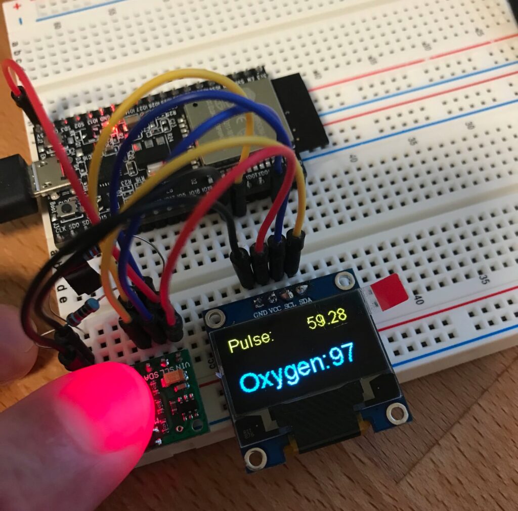
The wiring is shown on the first image, but they are partly obscured, so here is a table version:
| Wire | ESP32 | MAX30100 | SSD1306 |
| RED (Power) | 5V | VIN | VCC |
| YELLOW (I2C) | IO21 | SDA | SDA |
| BLUE (I2C) | IO22 | SCL | SCL |
| BLACK (Ground) | GND | GND | GND |
| 10k Pulldown resistor #1 | GND-SLC | ||
| 10k Pulldown resistor #2 | GND-SDA |
After completing this project, I picked up an inexpensive $15 fingertip pulse oximeter, and the readings are the same. The MAX30100 module has both LEDs mounted to the same side as the sensor, so the light reflects down from the finger. The standalone pulse oximeter has an LED (or two) above the fingernail shining down onto the sensor below. This won’t work with some nail polish, so the MAX30100 same side placement works for more users.
Project cost:
$10 ESP32 microcontroller
$8 SSD1306 OLED display
$12 MAX30100 pulse oximeter
Total: $30 Canadian, plus a breadboard, wires, and micro-USB cable that I already had from my IoT kit.
Update (October 3): I assembled my oximeter back in April and now that it’s October, decided to search for similar projects. COVID-19 has made oximeters a very popular project! Just keep in mind that the oximeter library specifically states it is not for medical use, and the oximeter may give incorrect readings if the LED settings or physical layout of the sensor is different. (The data sheet shows a sensor covered by a glass or plastic plate.) The sensor also only detects Hb saturation, and that could be either by O2 or CO, so someone with carbon monoxide poisoning would show a high saturation level (NOT O2) and could be in grave danger.